Field control devices

Measure and control water stations in the field with Metirius

Metirius is a flexible family of field devices that continuously measures and controls water supply systems. It manages pumps and valves on site at well, pumping, reservoir, network and wastewater stations; pump drive options range from 0.75 to 150 kW.

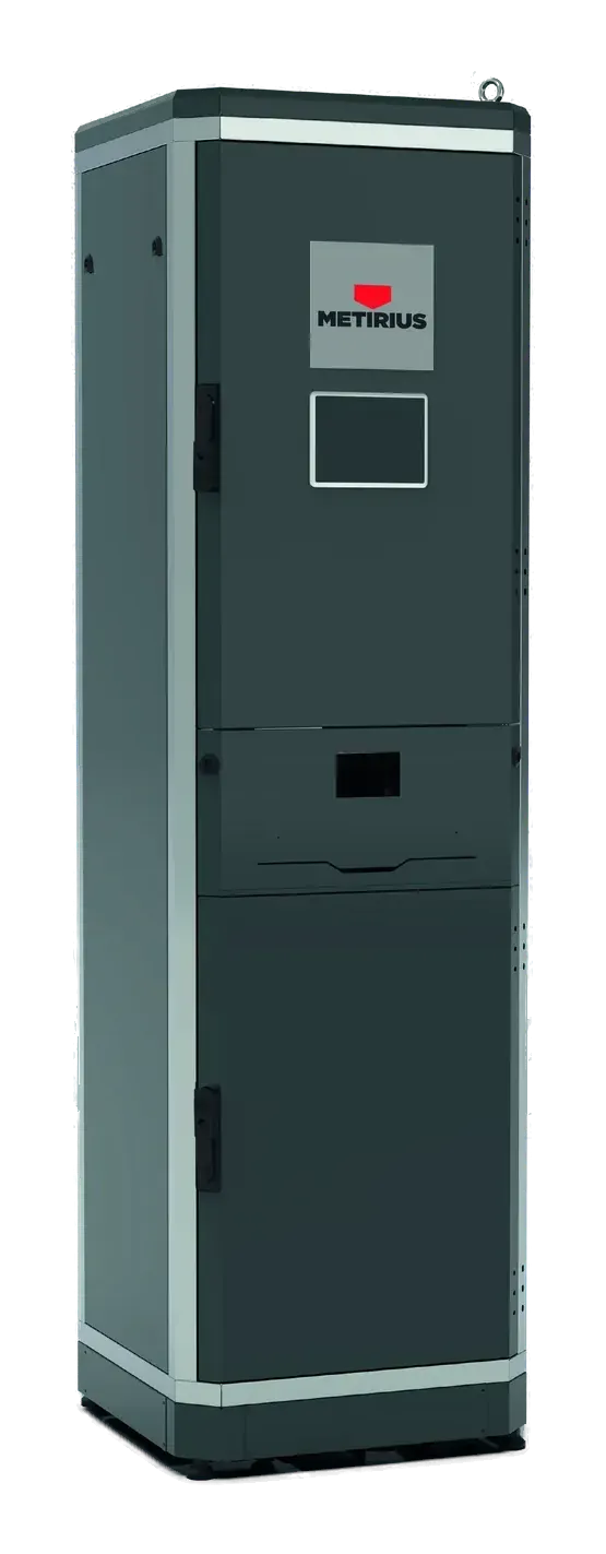
Anthracite Metirius field control panel with a display slot and stainless-steel edges, standing in front of a concrete wall

Which panel for which station

There is a Metirius model for every type of station along the water’s route. The panel’s drive, inputs and communication are configured to suit the station.

ModelStation and roleKey hardware
Metirius Well ProWell and pumping station: pump and drive; well level, flow, discharge pressure and energy0.75–150 kW VFD; energy analyser and current transformers
Metirius TankWater reservoir: reservoir level, valve and chlorine dosingInputs for two level sensors, two flow meters and a pressure sensor
Metirius WWWastewater lift station: wet well level and pumpsThree 0.75–75 kW VFDs; level sensor or one to six float switch inputs
Metirius NetworkNetwork valve control and measurement station: actuated valves, measurement and chlorineActuated valve control; flow meter and pressure sensor inputs
Metirius LimitDistribution zone (FCV and PCP chambers): flow into the zone and end-user pressureFCV: actuated valve and flow measurement; PCP: pressure measurement

The full input and output list for each model is on its own page.

Five models, one device family

Metirius devices communicate with each other: well, pumping station, reservoir and network panels can work together in the same operating chain.

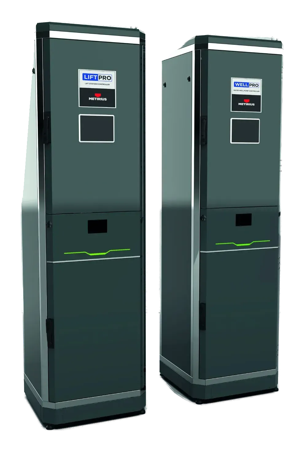
  • Two Metirius pump control panels side by side, for well and pumping station applications

    Well and pumping stations

    Metirius Well Pro

    Controls the pump through the drive; measures well level, flow, discharge pressure and energy.

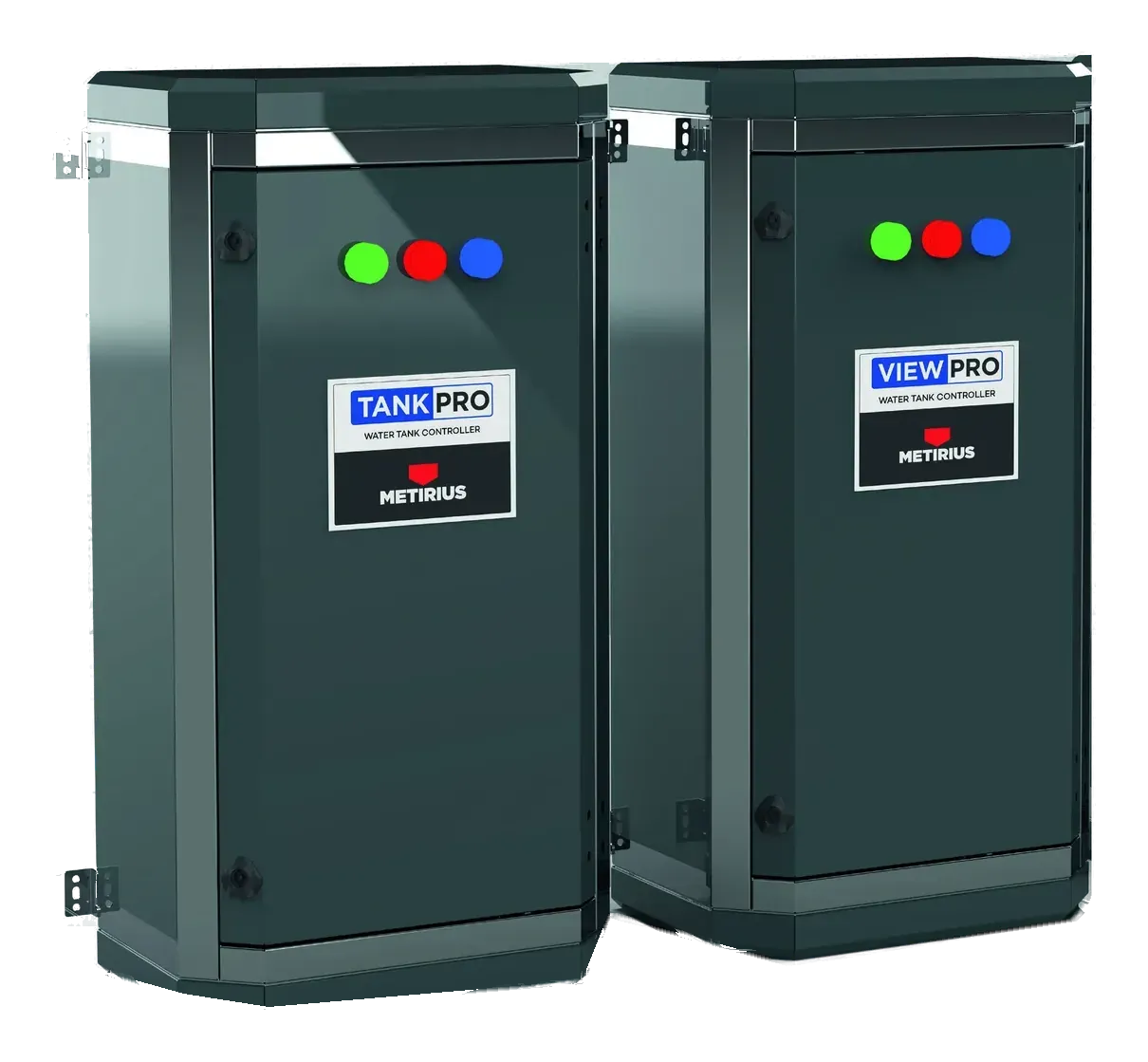
  • Two Metirius reservoir control panels with coloured status lights

    Reservoir stations

    Metirius Tank

    Monitors reservoir level, flow and pressure; manages the valve and chlorine dosing.

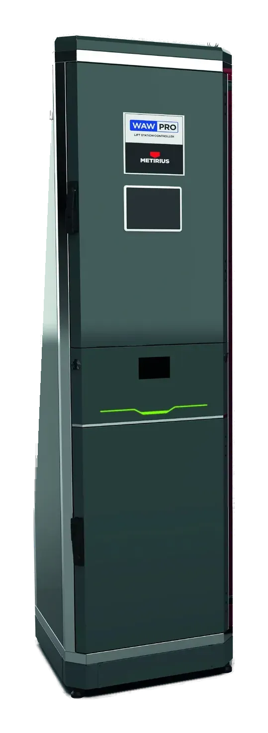
  • Metirius wastewater pump control panel with a display slot, in front of a concrete wall

    Wastewater lift stations

    Metirius WW

    Reads the wet well level and runs the pumps, with drives for up to three pumps.

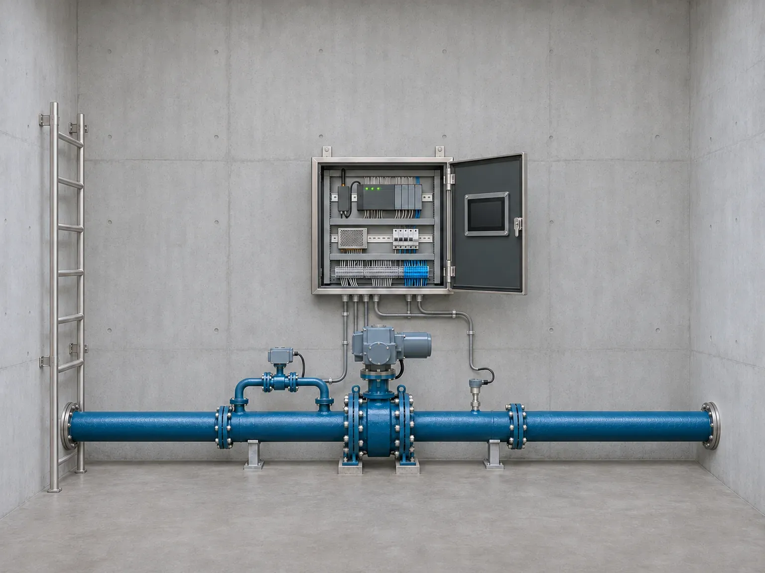
  • Field control panel with its door open in a valve chamber, and a pipeline with an actuated valve in front of it

    Network valve control and measurement stations

    Metirius Network

    Controls actuated valves, collects measurements and handles chlorine management.

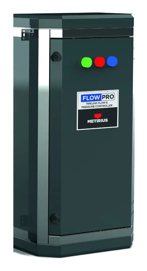
  • Wall-mounted Metirius flow and pressure control panel with coloured status lights

    Distribution · flow and pressure

    Metirius Limit

    Reduces water losses by coordinating flow control valves (FCV) and pressure control points (PCP).

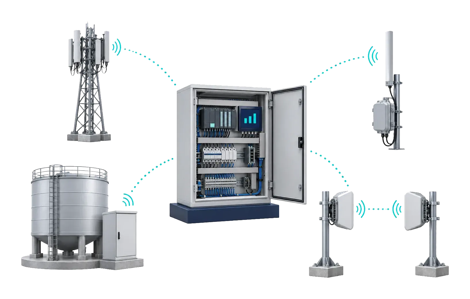
  • Panel, base station and long-range radio links

    Long-range communication

    Metirius RF-100 and RF-101

    The long-range communication devices of the Metirius family.

Shared architecture: from sensor to panel, from panel to the centre

All models share the same structure. Measurements are taken in the field, control decisions are made by the unit in the panel, and data is carried to the centre over the chosen link.

Field measurements

  • Level, pressure and flow
  • Voltage, current, power and energy
  • Temperature and vibration
  • pH, conductivity, chlorine and turbidity

Metirius panel

PLC, RTU or industrial PC; analogue and digital I/O, RS-485 and CAN bus; HMI display.

  • Pump and drive

    Operating parameters of the pump motor, via the drive.

  • Valve and chlorine

    Actuated valve position and chlorine dosing.

  • Communication

    GSM 4G/5G, LoRa/LoRaWAN or long-range point-to-point Wi-Fi.

  • ModbusTCP, RTU and ASCII
  • MQTTSparkplug B
  • Siemens S7S7-300, 400, 1200 and 1500
  • IEC 60870IEC 60870-5-104
  • IEC 61850MMS and IED functions
  • DNP3Supported
  • OPC UAClient and server

Inside the panel

The control unit, power components and field connections come together in a single panel assembly. The panels contain a programmable PLC, RTU or industrial PC, an HMI display, a GSM/RF communication unit and other electrical components; a sheet-metal or PVC enclosure is chosen to suit the operating conditions.

The terminal, wiring and connection layout takes account of operating conditions in the field, and the electronics are designed to withstand the noise generated by motors and drives. Sensors, communication and control components are selected to suit the use case.

  • Pump control systemsMetirius PUMP Base and Metirius PUMP EX
  • Reservoir control systemsMetirius TANK Base and Metirius TANK EX
  • Wastewater control systemsMetirius WASTE Base and Metirius WASTE EX
  • Long-range communication devicesMetirius RF-100 and Metirius RF-101
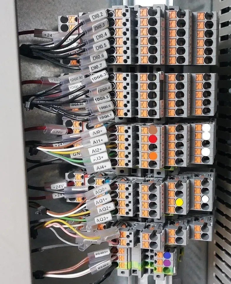
Labelled cables and terminal blocks inside a panel

Hardware shared across the device family

A panel’s hardware, sensors and supported protocols are set by the model and the project configuration.

ItemSpecification
Control unitIoT-enabled PLC, RTU or industrial PC; HMI display
MeasurementLevel, pressure and flow; voltage, current, power and energy via an energy analyser; equipment condition such as temperature and vibration; water quality such as pH, conductivity, chlorine and turbidity
Sensor interfaces4–20 mA hydrostatic level sensor and pressure transmitter; RS-485 electromagnetic flow meter. Support for ultrasonic flow meters and MID-certified flow meters
Digital readoutFlow meter, energy analyser and drive data over RS-485 or Ethernet: instantaneous flow, totaliser, reverse totaliser and water velocity
Energy analysisVoltage (V), current (A), active power (kW), reactive power (kvar), power factor and energy meter (kWh)
CommunicationGSM (4G/5G), LoRa/LoRaWAN and long-range point-to-point Wi-Fi; RS-485, CAN bus and Ethernet
Power200–500 VAC or 24 VDC input; isolation transformer; AC/DC battery charging system
EnclosureSheet metal or PVC, depending on the application

Configuration and commissioning for each application

Each panel is configured in four steps for the station where it will be installed.

  1. 01

    Measurement points

    The variables to be measured, the sensor connections and the measuring ranges are defined.

  2. 02

    Controlled equipment

    The functions of the pumps, drives and valves to be controlled are defined.

  3. 03

    Communication structure

    The connection method, protocol and access to the centre are chosen to suit the site.

  4. 04

    Operating parameters

    Sensors are calibrated; alarm thresholds and operating parameters are set to suit the operation.

Decisions in the field, monitoring at the centre

The field control algorithms run on the Metirius unit. Readings, alarms and reports are monitored in Predixi WIS on the web and in the mobile view.

A station’s readings are linked to the reservoir, pumping station and network views in the same project.

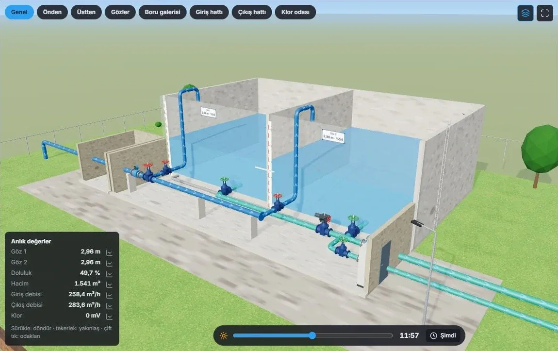
Three-dimensional Predixi WIS view of a reservoir station: pipes, valves and water level

A closer look

  • Metirius pump panel with its door open: variable-frequency drive, cable ducts and the communication module inside the door
  • Flow meter, pressure transmitter and level sensors connected to input modules
  • An ultrasonic flow meter measuring flow inside a pipe

Designed around your operation.

Tell us your station type, pump power and communication needs, and we will specify the panel together.